English
 English
 中文简体
中文简体
 Español
 Tiếng Việt
Get in touch
English
Get in touch
Jul 20, 2026
In the precision-driven world of mechanical engineering, torsion springs represent one of the most sophisticated categories of energy storage devices. Unlike linear-force springs that compress or extend along a single axis, torsion springs harness rotational energy through elastic torsional deformation. This fundamental difference opens up application possibilities across automotive assemblies, medical instruments, industrial machinery, and consumer electronics where angular force control is paramount.
As a dedicated manufacturer with decades of spring forming expertise, we engineer torsion springs that meet exacting torque specifications, fatigue life requirements, and environmental resistance standards. This comprehensive technical resource addresses the most critical questions engineers and procurement specialists ask when evaluating helical torsion components for their projects.
At its mechanical core, a torsion spring is a helical or spiral-shaped elastic element designed to store and release rotational energy. When opposing torques are applied to the spring's terminal arms, the wire cross-section undergoes bending stress rather than torsional shear stress—a common misconception in nomenclature. The stored elastic potential energy is proportional to the square of the angular displacement, following principles derived from classical beam theory.
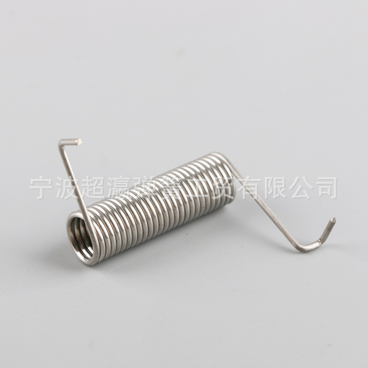
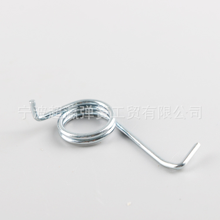
The geometric signature of torsion springs includes a coiled body section and two integral end legs that serve as torque application points. These end configurations range from straight tangential arms to radial hooks and compound bends, determining how the spring interfaces with mating components. The coil body acts as a torsion bar wound into a compact helical form, multiplying the effective length within a constrained radial envelope.
Manufacturing torsion springs demands precision wire forming equipment capable of maintaining tight tolerances on coil diameter, pitch consistency, and leg positioning. Our production lines utilize CNC multi-axis spring formers with real-time wire tension monitoring, ensuring that every coil exhibits uniform spring rate characteristics from the first cycle to the millionth.
Understanding the broader spring taxonomy provides essential context for selecting torsion springs over alternative elastic components. Mechanical springs are fundamentally categorized by their primary deformation mode and load direction. Each type occupies distinct functional niches in engineering design, and material selection criteria vary significantly across categories.
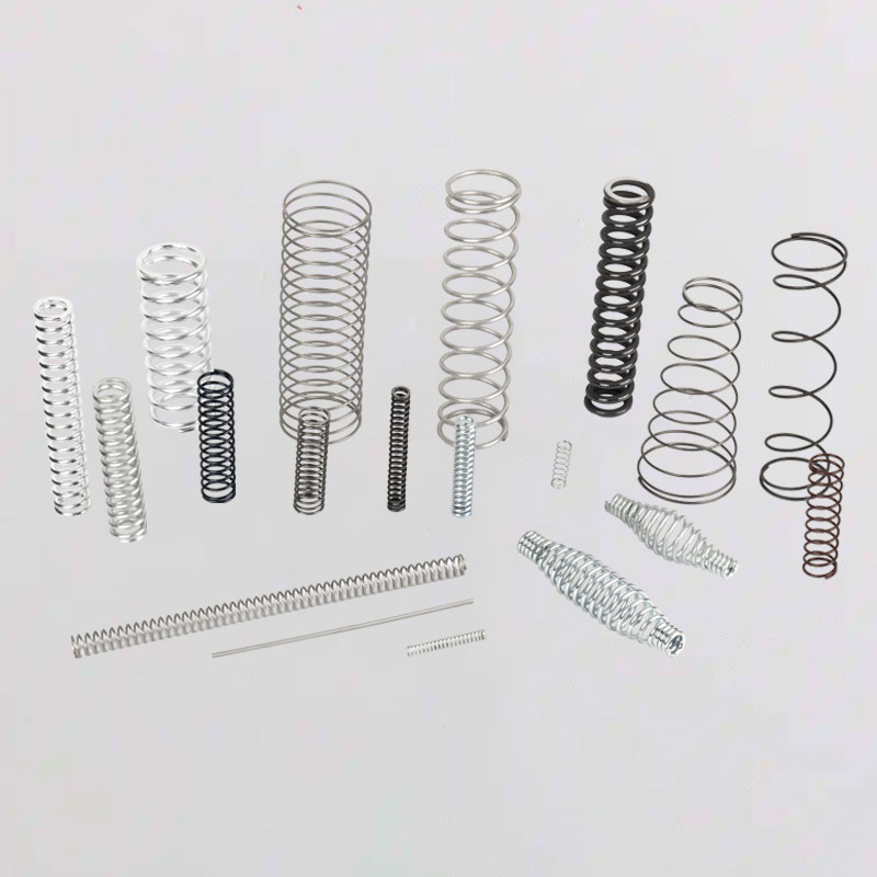
These are open-coil helical springs that resist axial compressive forces. When loaded, the coils move closer together until reaching solid height. Compression springs dominate suspension systems, valve actuation, and pen mechanisms. Their force-deflection relationship is linear within the elastic range, and they exhibit a natural self-limiting characteristic at solid height that prevents over-compression damage in properly designed assemblies.
Extension springs feature coils in close contact under no-load conditions, with initial tension holding the coils together. Upon stretching, the coils separate and generate a restoring force proportional to elongation. These springs require end hooks or loops for attachment, creating stress concentration points that often define the fatigue life limit. Common applications include garage door counterbalance systems, exercise equipment, and agricultural machinery.
torsion springs operate through angular deflection rather than linear displacement. The end legs rotate relative to each other, storing energy as the coil body twists. This mechanism makes them ideal for hinge return functions, clip retention, and torque-limiting applications. Unlike extension springs, torsion springs do not require hook formations that create stress risers, contributing to their superior fatigue performance in many duty cycles.
Constructed from multiple stacked metal plates of graduated lengths, leaf springs function as beam-bending elements. They distribute loads across a broad surface area and provide inherent damping through inter-leaf friction. While historically dominant in automotive rear suspensions, modern applications include heavy-duty truck suspensions, railway bogies, and certain industrial vibratory equipment where high load capacity and progressive spring rate are required.
| Parameter | Compression Springs | Extension Springs | torsion springs | Leaf Springs |
| Primary Load Direction | Axial compression | Axial tension | Radial torque | Transverse bending |
| Energy Storage Mechanism | Coil compression | Coil elongation | Wire bending stress | Beam deflection |
| Typical Spring Rate Unit | N/mm | N/mm | N·mm/degree | N/mm |
| End Configuration Complexity | Low (ground or plain ends) | High (hooks, loops) | Medium (varied leg forms) | Low (clamped or bolted) |
| Stress Concentration Risk | Low | High (at hooks) | Medium (at coil inner diameter) | Low |
| Self-Limiting Overload Protection | Yes (solid height) | No | Yes (with mechanical stops) | Partial |
| Common Fatigue Failure Mode | Coil buckling or shear | Hook fracture | Leg root cracking | Inter-leaf wear |
The operational physics of torsion springs centers on elastic bending deformation of the wire material. When torque is applied through the end legs, each coil segment behaves as a curved beam subjected to a bending moment. The bending stress distribution across the wire cross-section is not uniform due to curvature effects—the inner surface of the coil experiences higher stress than the outer surface, a phenomenon quantified by the curvature correction factor.
T = k × θ
Where T represents the applied torque in Newton-millimeters, k denotes the spring rate in torque per unit angular deflection, and θ is the angular displacement in degrees or radians. This linear relationship holds true within the material's elastic limit and assumes negligible friction between adjacent coils.
The spring rate k for helical torsion springs derives from beam bending theory adapted for curved members. For a round wire cross-section, the theoretical spring rate can be expressed as:
k = (d⁴ × E) / (10.2 × D × N_a)
In this formulation, d is the wire diameter, E is the modulus of elasticity of the spring material, D is the mean coil diameter, and N_a represents the number of active coils. The constant 10.2 incorporates unit conversion factors for typical engineering calculations when torque is expressed in N·mm and deflection in degrees.
The maximum bending stress in a torsion spring occurs at the inner surface of the coil body, where the curvature is most pronounced. Engineers must apply a Wahl correction factor or curvature coefficient to account for this stress magnification. For spring indices (D/d) between 4 and 12, the curvature coefficient K_i ranges approximately from 1.25 to 1.05, decreasing as the spring index increases.
The corrected bending stress formula becomes:
σ_max = K_i × (32 × T) / (π × d³)
Failure to apply this correction can result in designs that appear safe based on nominal stress calculations but experience premature fatigue failure in actual service conditions. Our engineering team performs finite element analysis on all critical torsion spring designs to validate hand calculations against three-dimensional stress distributions.
The category of torsion springs encompasses several distinct geometric configurations, each optimized for specific spatial constraints, torque profiles, and mounting requirements. Understanding these variations enables engineers to specify the most appropriate architecture for their mechanical assemblies.
The most prevalent configuration, consisting of a single helical coil with two projecting end legs. These torsion springs offer the simplest manufacturing path and lowest unit cost. End leg geometries include straight tangential arms (most common), radial arms for side-loading applications, and compound bends for clearance around adjacent components. Our manufacturing capability covers wire diameters from 0.2 mm to 20 mm in single-body configurations, with torque capacities ranging from 0.05 N·mm to 50,000 N·mm.
Also known as twin torsion springs, these components integrate two helical coils connected by a central bridge or torque arm. The symmetric design produces balanced torque output with minimal lateral thrust on the supporting shaft. Double torsion springs are extensively used in automotive seat recliners, printer paper feeders, and medical device hinges where space constraints preclude the use of two separate springs. The central bridge section requires careful stress analysis, as it experiences combined bending and torsional loading.
Constructed from flat strip material wound into a planar spiral, these springs store energy through the unwinding of the spiral rather than helical coil twisting. Spiral torsion springs deliver high torque output within an extremely compact axial envelope, making them indispensable in clock mechanisms, retractable badge reels, and seat belt retractors. The strip thickness typically ranges from 0.1 mm to 3 mm, with outer diameters extending to 300 mm for industrial counterbalance applications.
| Configuration Type | Optimal Wire/Strip Size | Max Angular Deflection | Primary Applications | Manufacturing Complexity |
| Single-Body Helical | 0.15 – 25 mm diameter | Up to 360° per coil | Door hinges, clip fasteners, industrial levers | Low to moderate |
| Double Torsion | 0.3 – 12 mm diameter | Up to 180° per coil | Automotive seats, printer mechanisms, medical hinges | Moderate to high |
| Spiral (Flat Strip) | 0.05 – 5 mm thickness | Up to 15 revolutions | Clocks, retractors, counterbalances, tape measures | High |
| Torsion Bars | 5 – 50 mm diameter | Up to 30° | Vehicle suspensions, anti-roll bars | Low |
Beyond geometric classification, torsion springs are further distinguished by their end leg configurations. Short tangential legs provide the most direct torque transmission path but require precise angular alignment during installation. Radial legs accommodate perpendicular loading directions and simplify assembly in confined spaces. Offset legs with compound bends navigate around obstructions while maintaining torque vector alignment. Our design engineering team collaborates directly with clients to develop custom leg geometries that integrate seamlessly with existing component architectures, eliminating the need for secondary adapter brackets or linkages.
Material selection for torsion springs represents one of the most consequential engineering decisions in the design process. The chosen alloy must simultaneously satisfy requirements for elastic modulus, tensile strength, fatigue resistance, corrosion immunity, temperature stability, and cost efficiency. No single material excels across all dimensions, necessitating trade-off analysis based on application-specific priorities.
The workhorse material for general-purpose torsion springs, music wire is a high-carbon steel cold-drawn to exceptional tensile strength levels exceeding 2000 MPa. Its fine pearlite microstructure, achieved through patenting and cold working, delivers outstanding fatigue performance in ambient environments. Music wire is cost-effective and readily available in diameters from 0.10 mm to 10 mm. Limitations include susceptibility to corrosion in humid or chemically aggressive environments and a maximum recommended service temperature of 120°C. For static or moderate-cycle applications, music wire torsion springs offer unmatched value.
When operating temperatures exceed 150°C or fatigue cycles exceed one million, chrome-silicon alloy steel becomes the material of choice. The addition of chromium and silicon enhances temper resistance and stress relaxation stability, maintaining spring rate consistency across temperature excursions from -40°C to +200°C. This material is standard for automotive torsion springs in engine compartments, exhaust system linkages, and underhood hinge mechanisms. Post-winding stress relief at 400–450°C optimizes the material's elastic properties.
Austenitic stainless steels provide excellent corrosion resistance in marine, food processing, and chemical exposure environments. While their tensile strength (typically 1700–1900 MPa in spring temper) falls slightly below music wire, the trade-off is justified when rust prevention is critical. 302/304 grades are non-magnetic and withstand sterilization cycles, making them standard for medical device torsion springs and surgical instruments. Passivation treatment after forming enhances surface chromium oxide layer integrity.
A precipitation-hardening stainless steel that achieves tensile strengths exceeding 2100 MPa after aging heat treatment. 17-7PH combines the corrosion resistance of austenitic grades with strength levels approaching music wire. This material is specified for aerospace torsion springs, satellite deployment mechanisms, and high-performance racing components where weight reduction and environmental resistance must coexist with extreme load capacity.
| Material Grade | Tensile Strength (MPa) | Elastic Modulus (GPa) | Max Service Temp (°C) | Corrosion Resistance | Relative Cost Index |
| Music Wire (ASTM A228) | 1900 – 2300 | 207 | 120 | Poor (requires plating) | 1.0 (baseline) |
| Chrome-Silicon (ASTM A401) | 1800 – 2100 | 207 | 220 | Poor (requires plating) | 1.4 |
| Stainless 302/304 | 1650 – 1900 | 193 | 260 | Excellent | 2.2 |
| Stainless 17-7PH | 1900 – 2200 | 204 | 315 | Excellent | 3.5 |
| Phosphor Bronze | 700 – 900 | 110 | 120 | Very Good | 3.0 |
| Beryllium Copper | 1100 – 1400 | 128 | 150 | Excellent | 5.0 |
| Inconel X-750 | 1400 – 1600 | 214 | 540 | Excellent | 8.5 |
Specialty materials expand the application envelope for torsion springs into extreme environments. Phosphor bronze and beryllium copper serve electrical connector applications where non-magnetic properties and low electrical resistance are mandatory. MP35N cobalt-nickel alloy meets the biocompatibility and fatigue requirements of implantable medical devices. Inconel X-750 withstands gas turbine temperatures exceeding 500°C while maintaining elastic response. Our material inventory spans over 40 certified alloys, with full traceability documentation and mill test reports available for regulated industries including aerospace and medical.
Accurate torque prediction forms the foundation of reliable torsion spring design. The governing equations bridge material properties, geometric dimensions, and operational loads to ensure that the spring performs within its elastic envelope throughout the design life. Engineers must account for both the idealized theoretical response and the real-world deviations introduced by manufacturing tolerances, material property scatter, and environmental factors.
T = k × θ
This equation states that the resisting torque T generated by the spring is directly proportional to the angular deflection θ from the free position. The proportionality constant k represents the spring rate, measured in torque units per degree of rotation. For a round-wire helical torsion spring, the spring rate can be calculated from fundamental material and geometric parameters.
The theoretical spring rate for a helical torsion spring with round wire derives from treating each active coil as a curved beam in bending:
k = (E × d⁴) / (64 × D × N_a) × (1 / conversion factor)
Where E is the modulus of elasticity, d is the wire diameter, D is the mean coil diameter, and N_a is the number of active coils. The conversion factor adjusts for angular units—when torque is in N·mm and deflection in degrees, the factor incorporates π/180. For practical engineering use with music wire (E = 207 GPa), this simplifies to:
k ≈ (d⁴ × E) / (10.2 × D × N_a) [N·mm/degree]
This formula assumes that all coils contribute equally to deflection and that coil spacing is sufficient to prevent contact between adjacent turns during operation.
The maximum stress in a torsion spring governs both static strength and fatigue life. The nominal bending stress without curvature correction is:
σ_nominal = (32 × T) / (π × d³)
However, the curved geometry of the coil concentrates stress on the inner surface. The curvature correction factor K_b for bending is:
K_b = (4C² - C - 1) / (4C × (C - 1))
Where C is the spring index (D/d). The corrected maximum stress becomes:
σ_max = K_b × (32 × T) / (π × d³)
For spring indices between 4 and 8, K_b ranges from approximately 1.25 to 1.10. Ignoring this correction can lead to designs with actual stresses 15% to 35% higher than calculated, resulting in unexpected early failure.
For cyclic loading applications, the Modified Goodman diagram provides a conservative estimate of fatigue safety. The criterion requires that the alternating stress component σ_a and mean stress component σ_m satisfy:
σ_a / S_e + σ_m / S_ut ≤ 1 / safety_factor
For music wire in spring-temper condition, the endurance limit S_e is approximately 35% to 38% of the ultimate tensile strength S_ut. A typical safety factor of 1.5 to 2.0 is applied for critical applications. Our testing laboratory performs rotary beam fatigue testing on material samples from each production lot to verify that actual endurance limits meet or exceed theoretical predictions.
| Parameter Change | Effect on Spring Rate (k) | Effect on Max Stress (σ) | Manufacturing Impact |
| Increase wire diameter (d) by 10% | Increase by 46% | Decrease by 25% | Higher forming force required |
| Increase coil diameter (D) by 10% | Decrease by 9% | Increase by 10% | Easier coiling, larger envelope |
| Increase active coils (N_a) by 10% | Decrease by 9% | No direct effect | Longer body length, more material |
| Use material with 10% higher E | Increase by 10% | No direct effect | May require different heat treatment |
| Decrease spring index (D/d) from 8 to 5 | Increase by 60% | Increase by 15% (K_b effect) | Difficult coiling, higher scrap rate |
Service life expectancy for torsion springs spans an enormous range—from millions of cycles in precision instruments to mere thousands in heavy industrial applications. The primary determinants of longevity are the maximum operating stress relative to material strength, the stress amplitude during each cycle, environmental exposure, and manufacturing quality consistency.
When a torsion spring is designed for infinite fatigue life—defined as exceeding 10 million cycles without failure—the maximum bending stress must be restricted to approximately 55% to 60% of the material's ultimate tensile strength. This conservative approach is standard for aerospace control surfaces, medical device actuators, and semiconductor manufacturing equipment where unexpected downtime carries extreme consequences. The trade-off is a larger, heavier spring compared to finite-life designs.
For duty cycles between 100,000 and 10 million operations, stress levels can be elevated to 65% to 70% of S_ut. This regime covers automotive door hinges, appliance latches, and office equipment mechanisms. Shot peening treatment becomes valuable in this range, inducing compressive residual stresses at the wire surface that counteract applied tensile bending stresses. Our shot peening process uses conditioned cut wire media at controlled intensity and coverage to achieve 15% to 20% improvement in allowable stress levels.
Applications with fewer than 10,000 total cycles—or static preload conditions—permit stress levels up to 80% of S_ut. This includes one-time deployment mechanisms, safety lock devices, and fixture clamping springs. The governing failure mode shifts from fatigue cracking to stress relaxation, where the material undergoes gradual plastic deformation under sustained load. At room temperature, carbon steel torsion springs loaded to 65% of S_ut will exhibit measurable free-angle drift within five years of continuous service.
| Application | Typical Stress Level (% S_ut) | Expected Cycle Life | Calendar Life (Years) | Critical Failure Mode |
| Residential garage door | 60 – 70% | 10,000 – 20,000 | 5 – 10 | Fatigue fracture at coil inner diameter |
| Automotive seat hinge | 55 – 65% | 50,000 – 100,000 | 10 – 15 | Leg root stress corrosion cracking |
| Medical instrument | 45 – 55% | 1,000,000+ | 10 – 20 | Stress relaxation (angle drift) |
| Aerospace actuator | 40 – 50% | 10,000,000+ | 20 – 30 | Surface pitting corrosion |
| Industrial clamp | 70 – 80% | 1,000 – 5,000 | 3 – 5 | Plastic deformation |
| Consumer electronics | 50 – 60% | 100,000 – 500,000 | 5 – 8 | Intermittent fatigue fracture |
Environmental degradation accelerates failure mechanisms in torsion springs. Corrosive atmospheres reduce the effective fatigue limit by initiating surface pits that act as crack nucleation sites. Elevated temperatures promote stress relaxation in carbon steels, with relaxation rates doubling approximately every 20°C above 100°C. Hydrogen embrittlement from electroplating processes can reduce the apparent tensile strength by 30% to 50% if not properly mitigated through baking treatments. Our quality assurance protocol includes 100% visual inspection, statistical sampling for torque verification, and environmental stress screening for critical applications.
Safety assessment of torsion springs requires comparative analysis against alternative spring types within specific application contexts. No spring category is inherently safe or unsafe in absolute terms; rather, safety emerges from the interaction between spring characteristics, system design, installation practices, and maintenance protocols. torsion springs exhibit distinct safety profiles that make them preferable for certain high-consequence applications.
The failure behavior of torsion springs tends toward gradual degradation rather than catastrophic fracture. As a torsion spring approaches its fatigue limit, it typically exhibits progressive free-angle change and reduced torque output—warning signs that maintenance personnel can detect during routine inspection. This contrasts with extension springs, where hook fractures occur suddenly and without prior indication, potentially releasing stored elastic energy in an uncontrolled manner.
In compression springs, overload failure manifests as permanent set or buckling, both of which are visually apparent. However, compression springs in valve applications can experience surge resonance that generates stress waves exceeding static design limits by 50% or more. torsion springs are immune to surge phenomena because their load application is fundamentally rotational rather than axial propagating.
The garage door application illustrates safety differentiation between spring types with particular clarity:
This physical constraint advantage has driven building codes in many jurisdictions to mandate torsion spring configurations for residential garage doors exceeding certain weight thresholds.
The safety of torsion springs is further enhanced by their compatibility with mechanical overload stops. Because the spring operates through angular deflection, hard stops can be positioned to limit maximum rotation to values below the material's yield angle. This positive mechanical limitation is more difficult to implement with extension springs, where the travel distance depends on door position and cable routing geometry. Our engineering team routinely integrates torque-limiting features and redundant retention structures into custom torsion spring assemblies for safety-critical medical and transportation applications.
The feasibility of manufacturing torsion springs in non-industrial environments depends entirely on the required precision, quantity, and performance specifications. While the fundamental process of winding wire around a mandrel is conceptually simple, achieving the dimensional tolerances, torque consistency, and fatigue life demanded by modern engineering applications requires specialized equipment and process control that is difficult to replicate outside a dedicated manufacturing facility.
Production-grade torsion springs are manufactured on CNC spring forming machines equipped with servo-controlled wire feed systems, rotating mandrels, and multi-axis bending tools. These machines maintain wire tension within ±2% throughout the forming cycle, ensuring consistent coil diameter and pitch. The forming process for a typical single-body torsion spring involves wire straightening, mandrel wrapping, end leg bending, and cut-off—all executed in a single automated sequence. Machine cycle times range from 2 seconds for small wire diameters to 30 seconds for heavy industrial springs.
After forming, torsion springs require stress relief heat treatment to stabilize the microstructure and establish dimensional memory. For music wire, this involves heating to 230–260°C for 20–30 minutes in a controlled atmosphere furnace to prevent oxidation. Chrome-silicon alloys demand higher temperatures (400–450°C) to achieve optimal temper resistance. Temperature uniformity within ±5°C across the furnace chamber is essential—local overheating creates brittle zones that become crack initiation points under cyclic loading. DIY heat treatment using uncontrolled ovens or torches cannot achieve this precision.
Shot peening, a critical process for high-cycle torsion springs, requires precise control of media size, velocity, and coverage angle. Our shot peening equipment uses Almen strip testing to verify intensity compliance per SAE J443 standards. Post-treatment quality verification includes 100% torque testing on calibrated torsion test stands, free angle measurement with digital protractors (±0.5° accuracy), and dimensional inspection using optical comparators. Statistical process control charts track critical parameters across production lots to detect drift before out-of-specification parts are produced.
| Capability | DIY / Workshop | Professional Manufacturer |
| Wire diameter range | Limited to hand-bendable sizes (typically >1 mm) | 0.1 mm to 30 mm, all alloy grades |
| Coil diameter tolerance | ±0.5 mm or worse | ±0.05 mm for precision grades |
| Free angle tolerance | ±5° to ±10° | ±1° to ±3° standard, ±0.5° precision |
| Torque consistency (Cpk) | Not measurable without test equipment | Cpk ≥ 1.33 standard, Cpk ≥ 1.67 for critical |
| Heat treatment control | Uncontrolled, risk of overheating | Atmosphere-controlled furnaces, ±3°C uniformity |
| Shot peening | Not feasible | Automated with Almen intensity verification |
| Surface finish | Oxidized, rough | Passivated, plated, or coated per specification |
| Material certification | Unavailable | Full mill test reports and lot traceability |
| Volume capability | Units to tens per day | Thousands to millions per month |
For prototyping and very low-volume applications, hand-wound torsion springs may provide functional proof-of-concept samples. However, transitioning to production volumes demands the repeatability and process capability that only automated manufacturing can deliver. Our facility operates 24/7 production schedules with changeover times under 30 minutes, enabling economical production runs from 100 pieces to millions. Every production lot is accompanied by a certificate of conformance documenting material heat number, torque test results, dimensional measurements, and surface treatment verification.
As a vertically integrated spring manufacturer, we maintain complete control over every production stage from raw material receipt to final inspection. Our manufacturing campus houses over 60 CNC spring forming machines, 12 heat treatment lines, 8 shot peening systems, and a metrology laboratory equipped with CMM and optical measurement systems. This infrastructure enables us to produce torsion springs that meet the stringent requirements of ISO 9001, IATF 16949, and AS9100 quality management systems.
Our latest-generation spring formers feature 12 servo-controlled axes that manipulate wire through complex three-dimensional bending sequences. Wire feed resolution of 0.01 mm enables the production of micro torsion springs for hearing aids and catheter deployment devices. For heavy-duty applications, hydraulic-assisted forming heads process chrome-silicon wire up to 25 mm diameter with forming forces exceeding 50 kN.
Stress relief and tempering operations are performed in atmosphere-controlled batch furnaces with nitrogen purging to prevent surface decarburization. Temperature profiles are logged at 10-second intervals and stored for 10 years to support traceability requirements. For precipitation-hardening alloys like 17-7PH, our vacuum furnaces achieve solution treatment at 1065°C followed by controlled aging at 480°C.
Surface finish directly impacts fatigue performance and environmental resistance. Our capabilities include electropolishing for medical-grade stainless steel torsion springs, zinc-phosphate coating for corrosion protection in automotive underhood applications, and PTFE-based dry film lubrication for low-friction hinge assemblies. Shot peening intensity is verified per SAE J443 using A-type Almen strips.
The quality laboratory operates torque test stands with 0.1% accuracy load cells and rotary encoders resolving to 0.1 degrees. Statistical sampling plans follow ANSI/ASQ Z1.4 general inspection levels. Material verification includes optical emission spectroscopy for alloy composition confirmation and Rockwell hardness testing on every heat treatment batch.
torsion springs serve as critical functional elements across virtually every industrial sector. Our engineering team has developed application-specific solutions that address the unique challenges of torque delivery in demanding environments.
Vehicle assemblies rely on torsion springs for door check mechanisms, seat recliner returns, glove box hinges, and throttle return functions. Automotive-grade springs must withstand temperature cycles from -40°C to +150°C, vibration frequencies up to 2000 Hz, and salt spray exposure per ASTM B117.
Surgical staplers, laparoscopic instrument jaws, and implantable drug delivery systems incorporate miniature torsion springs with wire diameters below 0.3 mm. These components require biocompatibility per ISO 10993, passivation to ASTM A967, and 100% torque verification.
Aircraft control surface return springs, satellite deployment mechanisms, and weapons system safeties demand torsion springs with documented pedigree back to material melt. AS9100 quality system compliance and NADCAP accreditation for special processes are standard offerings.
Laptop hinge mechanisms, smartphone flip covers, and wearable device clasps utilize micro torsion springs that deliver consistent tactile feedback over 100,000+ actuation cycles. Our design team routinely develops springs fitting within 3 mm radial envelopes while maintaining ±10% torque tolerance.
Conveyor system tensioners, packaging machine grippers, and textile loom components employ heavy-duty torsion springs handling torque loads exceeding 500 N·m. We design custom retention housings that prevent coil unwinding in the event of fracture.
Planter row unit down-pressure systems, harvester reel tines, and irrigation valve actuators expose torsion springs to abrasive dust, moisture, and UV radiation. Our agricultural spring designs incorporate zinc-aluminum flake coatings providing 1000+ hours salt spray protection.
Every mechanical assembly presents unique constraints on envelope dimensions, torque profile, mounting geometry, and environmental exposure. Our engineering department provides complimentary design consultation for torsion spring projects, translating functional requirements into manufacturable specifications.
Engineers review torque specifications, angular travel requirements, installation envelope, duty cycle expectations, and environmental conditions. Material recommendations are provided based on operating temperature, corrosion exposure, and fatigue life targets.
CAD models are developed with parametrically driven geometry that updates automatically when design variables change. Finite element analysis validates stress distributions, identifies potential interference during deflection, and predicts fatigue life under specified loading spectra.
First-article samples are manufactured on production-equivalent equipment to validate manufacturability. Torque-angle curves are measured on calibrated test stands and compared against design predictions. Dimensional reports document every critical characteristic.
Process capability studies verify that production equipment can consistently meet specification tolerances. Statistical process control plans are established for ongoing production monitoring. Full PPAP documentation packages are prepared for regulated industries.
Our rapid prototyping service delivers functional torsion spring samples within 5 to 10 business days from design finalization. For urgent projects, expedited programs compress this timeline to 48 hours for standard materials and geometries.
While both store energy through torsional deformation, a torsion spring is a coiled helical form that multiplies the effective torsional length within a compact radial package. A torsion bar is a straight solid bar that twists along its longitudinal axis. Torsion bars are used in vehicle suspensions where space permits linear installation, while torsion springs are preferred when the available envelope is constrained to a cylindrical volume.
No. torsion springs are specifically designed to resist rotational forces applied to their end legs. Applying axial compression or tension would cause the coils to collapse or separate unpredictably, potentially damaging the spring and creating a safety hazard. Always match the spring type to the intended load direction.
The free angle is measured between the two end legs when the spring is in its unloaded condition. Place the spring on a flat surface with one leg aligned to a reference line. Measure the angular displacement to the second leg using a digital protractor or optical comparator. Standard tolerances are ±3° for commercial grade and ±1° for precision grade.
Stress relaxation is the primary mechanism, occurring when the material undergoes slow plastic deformation under sustained load even at stresses below the yield point. The rate of relaxation increases with temperature—carbon steel torsion springs held at 65% of ultimate tensile strength will exhibit measurable free-angle change within months at 100°C. Chrome-silicon and precipitation-hardening stainless steels offer superior relaxation resistance for high-temperature applications.
Yes. The winding direction must match the torque application direction to prevent the spring from unwinding. A right-hand wound torsion spring subjected to clockwise torque (viewed from one end) will tighten the coils, while counter-clockwise torque will tend to unwind them. Specifying the incorrect winding direction can result in immediate coil separation and loss of spring function.
For carbon steel torsion springs, zinc plating with chromate conversion coating provides economical corrosion protection for indoor and mild outdoor environments. For marine or chemical exposure, electroless nickel plating offers superior barrier protection without the hydrogen embrittlement risk associated with electrolytic processes. Stainless steel grades eliminate the need for plating but may still benefit from passivation to restore the chromium oxide layer after forming.
The engineering of torsion springs demands mastery of material science, mechanical design, and precision manufacturing. From answering What is the torsion spring? at the conceptual level to resolving What is the formula for calculating the torque of a torsion spring? in quantitative design practice, every phase of development requires rigorous technical discipline. The interplay between spring geometry, material selection, stress analysis, and manufacturing process control ultimately determines whether a torsion spring will deliver reliable service for decades or fail prematurely under operational loads.
Our manufacturing organization combines advanced CNC forming technology, metallurgical expertise, and comprehensive quality systems to produce torsion springs that meet the exacting standards of automotive, medical, aerospace, and industrial markets. Whether your project requires a single prototype for validation or millions of pieces for annual production, our engineering and manufacturing teams are equipped to deliver components that perform consistently from the first cycle to the last. Submit your specifications through our technical inquiry portal, and our application engineers will respond with design recommendations, material options, and quotation within 24 hours.
Related Products
Contact us
Factory Address
No. 8, Taoyuan South Road, Wuyuqiao, Henghe Town, Cixi City, Ningbo, China
Phone
+86-188 6787 1218+86-574-62605393
QR CODE
 Wholesale Stainless Steel Coil Springs Manufacturers