English
 English
 中文简体
中文简体
 Español
 Tiếng Việt
Get in touch
English
Get in touch
Jul 27, 2026
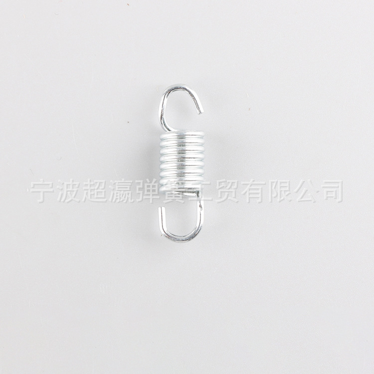
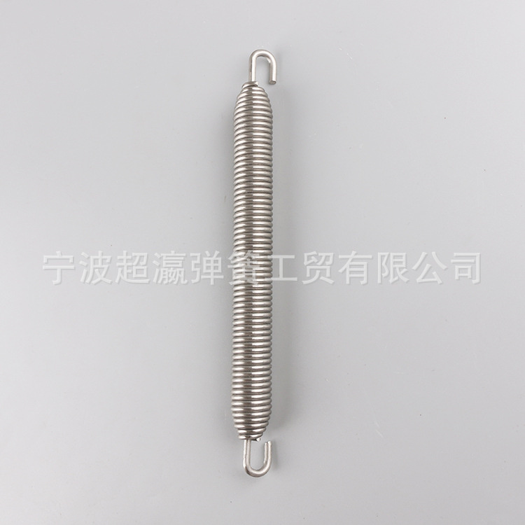
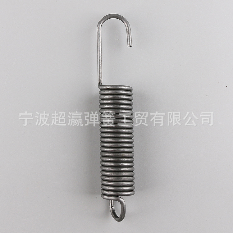
A Stainless Steel Extension Springs product is rarely selected on wire diameter alone. Buyers evaluating a plug cover tension spring, a switch return spring, or a battery cover spring are really asking a chain of practical questions: will the coil hold its force after ten thousand cycles, will the finish survive a coastal warehouse, and can the free length be adjusted without re-tooling the whole part. This section works through those practical questions directly, moving from where an Extension Spring is actually installed on a finished product, through material grade selection, force behavior, the manufacturing sequence, customization options, and the questions engineers ask most often before placing a drawing on the table.
A plug cover extension spring is a small component, but it sits inside an assembly where failure is visible immediately — a loose cover, a switch that does not snap back, a lock plate that rattles. The application list below reflects the installation points where this spring type is most commonly specified, based on the mechanical role it plays rather than the industry label alone.
Port covers, SIM tray latches, and connector caps use a small-diameter extension spring to keep a flap seated against dust and moisture while still allowing single-hand release.
Deadbolt return mechanisms and latch bolts rely on consistent tension so the bolt returns to the same position every time the handle is released, cycle after cycle.
Glovebox catches, fuel-cap covers, and cup-holder mechanisms need a spring that keeps working after long exposure to under-hood or cabin temperature swings.
Battery door springs must resist corrosion from occasional electrolyte exposure while still returning the cover to a flush, sealed position.
Recessed and track lighting housings use small tension springs to hold a lens or trim ring in place without visible fasteners.
Toggle and rocker switch assemblies depend on a spring with a stable spring rate so the actuation feel stays identical across the full production run.
Recliner and sofa-bed hardware use longer extension springs to store and release mechanical energy smoothly during repeated folding motion.
Kickstand and derailleur return springs must keep tension consistent through vibration, road grit, and outdoor humidity.
Ejector return springs in molds and cover-retention springs in small appliances both call for tight free-length tolerance so assembly stays repeatable.
Not every stainless steel wire performs the same way once it is coiled under tension. The three grades below are the ones most frequently requested for an Extension Spring project, and each one carries a different balance of corrosion resistance, strength, and magnetic behavior.
| Material Grade | Corrosion Resistance | Tensile Strength | Magnetic Behavior | Typical Application |
| Stainless Steel 304 | Good general resistance | Medium-high | Slightly magnetic after cold forming | Indoor electronics, switches, lock hardware |
| Stainless Steel 316 | High, including chloride exposure | Medium-high | Slightly magnetic after cold forming | Outdoor fixtures, marine-adjacent hardware |
| Stainless Steel 301 | Moderate | High | Magnetic | High-cycle mechanisms needing extra spring force |
A plug cover extension spring installed indoors, such as inside a communication enclosure or a switch housing, generally performs well in 304 grade wire. A spring exposed to washdown, coastal air, or outdoor moisture is better matched to 316 grade, since its added molybdenum content resists pitting corrosion that chloride exposure can cause over time. 301 grade is reserved for mechanisms where higher spring force is required from a smaller wire diameter, accepting a slightly lower corrosion margin in exchange for strength.
The pulling force an Extension Spring delivers at a given extension length is governed by four variables working together rather than any single dimension. Wire diameter has the strongest influence — a small increase in wire thickness raises spring rate sharply, because stiffness scales with the fourth power of wire diameter in torsion-based coil behavior. Coil diameter works in the opposite direction: a larger mean coil diameter lowers spring rate for the same wire size, since the wire experiences more leverage around a wider loop. The number of active coils spreads the same total deflection across more turns, which softens the force curve, while the shear modulus of the chosen stainless steel grade sets the underlying stiffness ceiling for the material itself.
Because these variables interact, two extension springs with an identical outer diameter can deliver noticeably different pull forces depending on wire thickness and coil count alone. This is why a drawing that specifies free length and outer diameter without confirming wire diameter and coil count still leaves the actual working force undefined — all four figures need to be fixed together before a plug cover spring can be trusted to return to the same position across a full production batch.
A finished Extension Spring passes through a defined sequence of operations before it reaches a customer's assembly line. Each stage below directly affects a different aspect of final performance.
Incoming stainless steel wire is checked for diameter consistency and surface defects before coiling begins, since any inherited flaw carries through the entire coil.
Precision coiling machines form the wire into the specified outer diameter and pitch, holding coil count and spacing within tight repeatable tolerance.
A controlled low-temperature heat cycle removes internal stress introduced during coiling, stabilizing the spring rate before the coil is put into service.
Hooks, loops, or specialty tail shapes such as a Spanish tail end are formed to match the mating component, whether that is a plug cover lip or a mounting pin.
Passivation or electro-polishing removes surface iron contaminants and restores the passive oxide layer that gives stainless steel its corrosion resistance.
Outer diameter, free length, and end orientation are measured against the drawing using calibrated gauges before the batch moves forward.
Sample springs are pulled through tensile and cyclic fatigue testing to confirm the force curve matches the design target across repeated extension.
Springs are counted, bagged, or reeled according to the assembly line format required, protecting hooks and tails from tangling in transit.
Because a plug cover spring is almost always a non-standard part matched to a specific enclosure, most projects begin from a drawing rather than a catalog number. The dimensions and features below are the ones most commonly adjusted from project to project.
Adjusted to fit the available cavity inside the plug cover or housing, from compact sub-3mm assemblies to larger mechanical fixtures.
Selected to hit a target spring rate, balancing pull force against the space and torque limits of the surrounding mechanism.
Set to match the resting position required by the assembly, with tolerance held tight enough to keep every unit interchangeable.
Formed as a hook, loop, straight tail, or specialty shape such as a Spanish tail, matched precisely to the mating pin or slot.
Wound right-handed or left-handed depending on how the spring needs to engage with the rest of the mechanism during assembly.
Passivated, electro-polished, or left in a natural mill finish, depending on the corrosion resistance and appearance requirement.
An Extension Spring is designed to resist being stretched, storing energy as it is pulled apart and pulling itself back to rest length once released. A compression spring works in the opposite direction, resisting being pushed together. A plug cover spring is an extension type because it must pull the cover back into a closed, seated position.
In most outdoor environments, 304 or 316 grade stainless steel wire performs reliably without an additional coating, since the passive oxide layer on the surface already provides corrosion protection. In environments with heavy salt spray or constant chemical exposure, 316 grade is the safer baseline choice.
Plug cover and small enclosure applications commonly use wire diameters in the fine range, since the spring needs to fit inside a compact cavity while still providing enough force to keep a cover seated. The exact figure depends on the target pull force and the available coil diameter.
Stainless steel extension springs generally operate without lubrication, since the material's natural surface properties keep friction low during normal extension and retraction. Lubrication is more relevant to carbon steel springs, where it also serves a corrosion-prevention role that stainless steel does not require.
With CNC coiling and calibrated dimensional inspection, free length and outer diameter can be held to tight tolerances suitable for automated assembly lines, though the achievable figure depends on wire diameter, coil count, and the specific end shape requested.
A Spanish tail end distributes stress differently than a standard hook, which can reduce the risk of stress concentration at the point where the coil transitions into the end. It also allows the spring to be anchored in tighter or irregularly shaped mounting spaces common in plug cover assemblies.
Extension spring design does not happen in isolation from established mechanical standards. The reference points below are commonly used during drawing review and testing to confirm a stainless steel extension spring will behave predictably once it reaches an assembly line.
| Reference | Scope | Relevance to Extension Springs |
| ASTM A313 | Stainless steel spring wire specification | Defines chemical composition and mechanical property ranges for spring-grade stainless wire |
| ISO 683-14 | Spring steel classification | Used as a cross-reference when matching wire properties across regional material standards |
| DIN EN 10270-3 | Stainless steel spring wire dimensions and tolerances | Guides wire diameter tolerance bands during coiling and quality inspection |
Reviewing a plug cover extension spring drawing against these reference points before production begins helps confirm that wire diameter, coil geometry, and end shape will translate into the exact pull force and fatigue life the assembly requires, reducing the chance of a mismatch showing up only after tooling has already been committed.
Related Products
Contact us
Factory Address
No. 8, Taoyuan South Road, Wuyuqiao, Henghe Town, Cixi City, Ningbo, China
Phone
+86-188 6787 1218+86-574-62605393
QR CODE
 Wholesale Stainless Steel Coil Springs Manufacturers